
Category: sketches
Recycling conference catalogs


I found a great (re)use for leftover conference catalogs.
Corporate aura

Eric Schmidt, CEO of Google Inc., at Humboldt University, Berlin, Germany, February 16, 2011
Fritzing for designing electronics

I just discovered Fritzing; an application for designing electronic projects and laying-out PCBs. The software is dependable, has a useful website with tutorials and project examples, and they are even starting a fabrication service in Dec 2010. Fritzing was started in August 2007 by the Interaction Design Lab at the University of Applied Sciences Potsdam, Germany.

When you launch the software you begin with a breadboard. Then you drag components from a large list on the right, choosing options for the parts. Adjusting rotation, color, and placement is all fairly intuitive. While I found working with “2.5D” perspective is a little awkward at first, you get used to it. For output, you can select between Breadboard, Schematic, and PCB views on the bottom right.

Here’s a design to accompany a previous sketch, Fading an LED with PWM and a Potentiometer

New Automata sitemaps
A deconstruction of defense contractor website data structures.


You Never Close Your Eyes Anymore (mock-installation-in-pa-shop)
Here are a couple installation shots of You Never Close Your Eyes Anymore leading up to the AC Direct installation in New York. Everyone should be so lucky to have a retired shop teacher for a father in law!


Schematic for You Never Close Your Eyes Anymore
“Open sourcing” the schematic for the electronic components for You Never Close Your Eyes Anymore.

Products:
RBBB boards (Arduino clone)
custom-designed circuits
– female headers
– TIP31 transistor
– 6-wire Unipolar Stepper motor (48 step Nippon Electric Pulse Motor)
– ULN2803A Darlington Array
– hook-up wire
– various resistors
– LEDs
used camera lenses
aluminum “flat bar”
hose clamps
rubber wine corks
various mounting hardware
More production photos
More photos from You Never Close Your Eyes Anymore production.


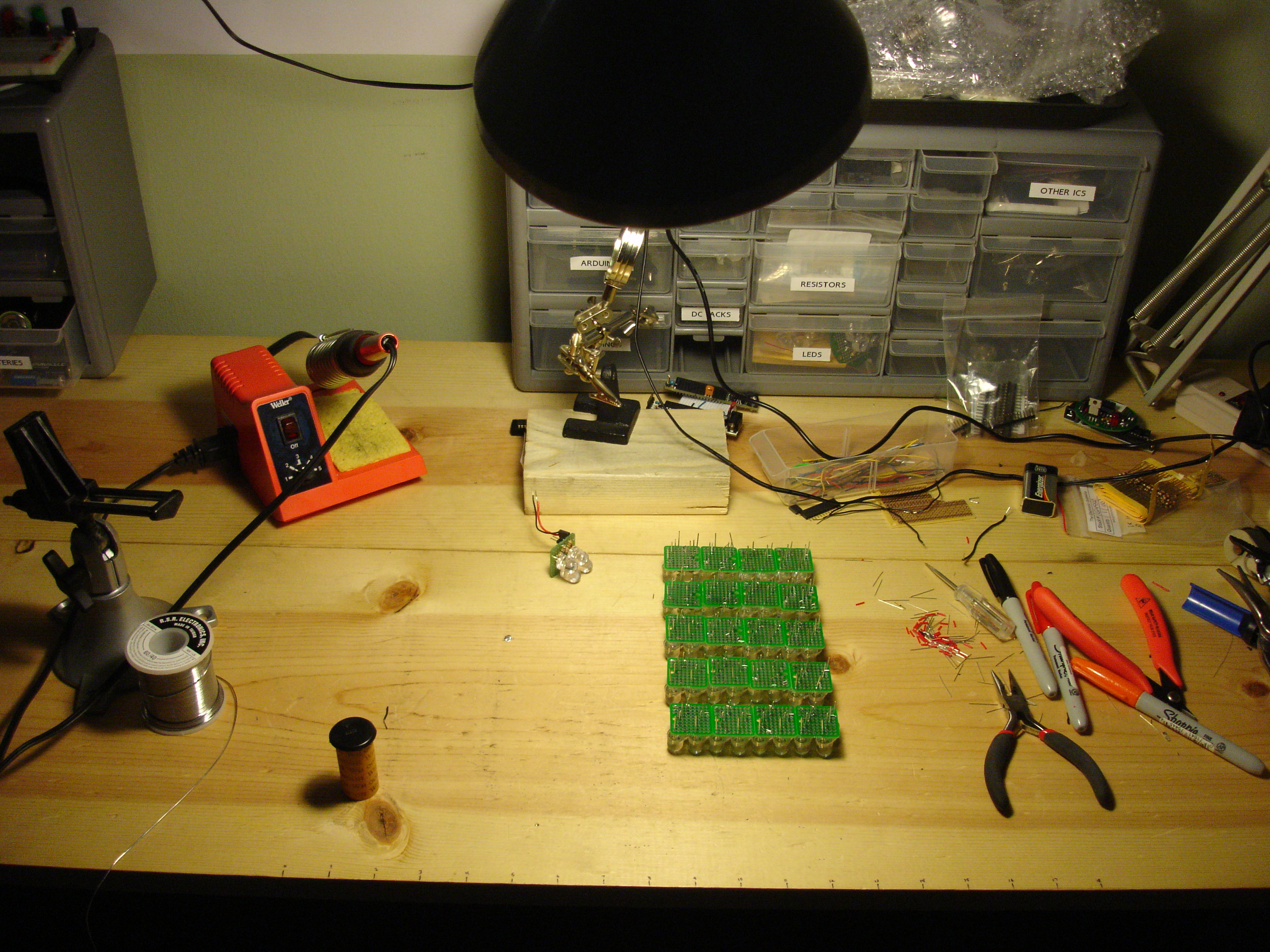


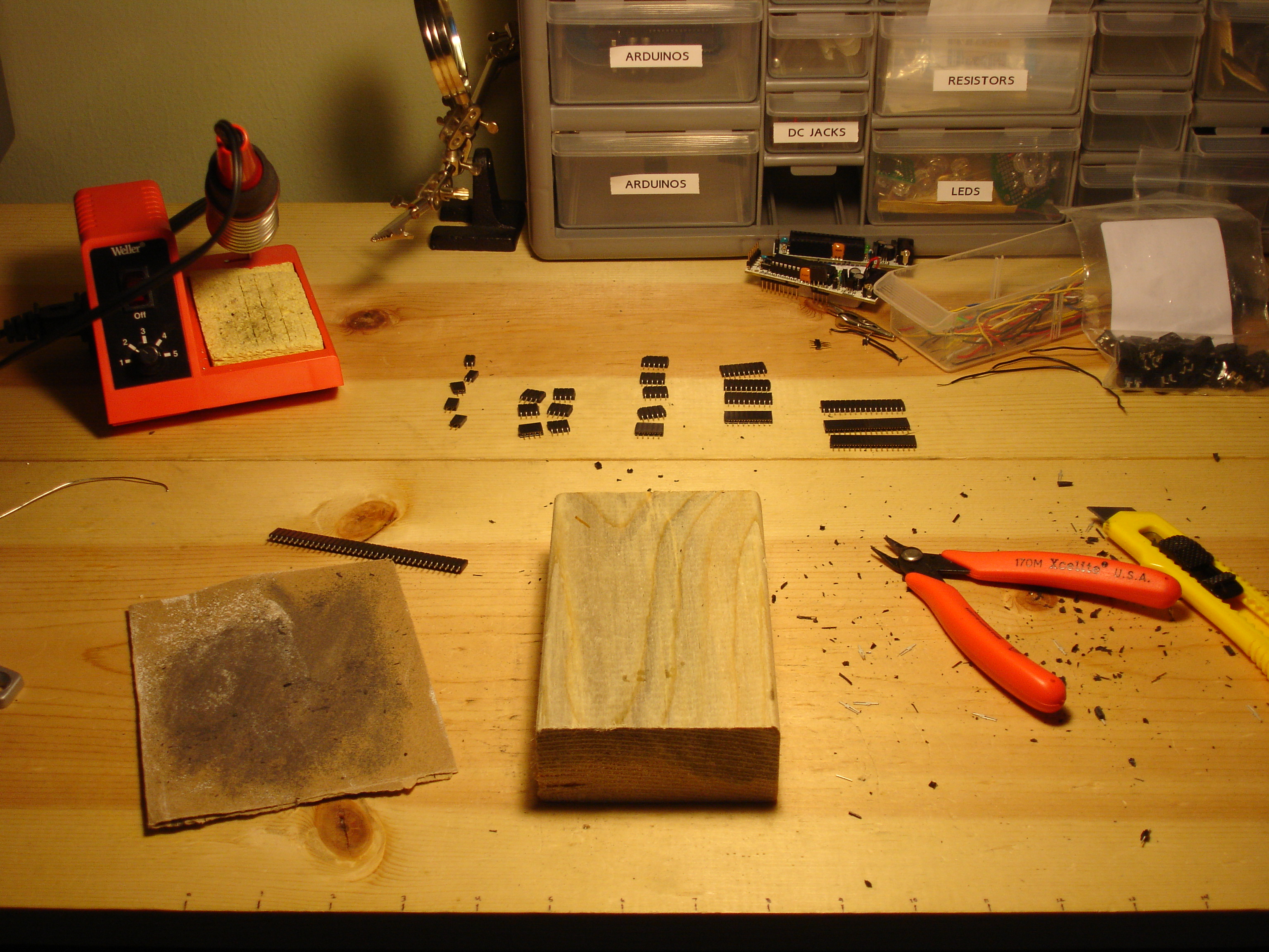


Mass Production

Preparing for show at AC Institute in New York.
Fading an LED with PWM and a Potentiometer
Using a potentiometer and PWM on an Arduino to fade an LED.
-
-
/* POT to LED test -> by Owen Mundy March 11, 2010
-
from: http://itp.nyu.edu/physcomp/Labs/AnalogIn
-
—————————————————————*/
-
-
int potPin = 0; // Analog input pin that the potentiometer is attached to
-
int potValue = 0; // value read from the pot
-
int led = 9; // PWM pin that the LED is on. n.b. PWM 0 is on digital pin 9
-
-
void setup() {
-
// initialize serial communications at 9600 bps:
-
Serial.begin(9600);
-
// declare the led pin as an output:
-
pinMode(led, OUTPUT);
-
}
-
-
void loop() {
-
potValue = analogRead(potPin); // read the pot value
-
analogWrite(led, potValue/4); // PWM the LED with the pot value (divided by 4 to fit in a byte)
-
Serial.println("hello"); // print the pot value back to the debugger pane
-
delay(10); // wait 10 milliseconds before the next loop
-
}
-
Here is the schematic for the above project.
Using PWM and a potentiometer to fade an LED and drive a stepper motor, powered by a Boarduino RBBB.
-
-
/*
-
Owen Mundy
-
July 29, 2009
-
-
p. 262 of Physical Computing
-
Using BBB to run stepper motor by manually moving steppers
-
-
*/
-
-
int pin1 = 3; // PWM
-
int pin2 = 5; // PWM
-
int pin3 = 6; // PWM
-
int pin4 = 9; // PWM
-
int ledpin = 13; // LED
-
int led = false; // LED monitor
-
int motor_time_lapse = 80;
-
-
int potPin = 0; // Analog input pin that the potentiometer is attached to
-
int potValue = 0; // value read from the pot
-
int ledPotPin = 11; // PWM pin that the LED is on. n.b. PWM 0 is on digital pin 9
-
-
-
void setup()
-
{
-
pinMode(pin1, OUTPUT); // sets the pin as output
-
pinMode(pin2, OUTPUT); // sets the pin as output
-
pinMode(pin3, OUTPUT); // sets the pin as output
-
pinMode(pin4, OUTPUT); // sets the pin as output
-
pinMode(ledpin, OUTPUT); // sets the pin as output
-
-
// initialize serial communications at 9600 bps:
-
Serial.begin(9600);
-
// declare the led pin as an output:
-
pinMode(ledPotPin, OUTPUT);
-
}
-
-
void loop()
-
{
-
potValue = analogRead(potPin); // read the pot value
-
analogWrite(ledPotPin, potValue/4); // PWM the LED with the pot value (divided by 4 to fit in a byte)
-
Serial.println(potValue);
-
-
digitalWrite(pin1, HIGH); // on
-
digitalWrite(pin2, LOW); // off
-
digitalWrite(pin3, HIGH); // on
-
digitalWrite(pin4, LOW); // off
-
delay(motor_time_lapse); // wait
-
-
-
digitalWrite(pin1, LOW); // off
-
digitalWrite(pin2, HIGH); // on
-
digitalWrite(pin3, HIGH); // on
-
digitalWrite(pin4, LOW); // off
-
delay(motor_time_lapse); // wait
-
-
digitalWrite(pin1, LOW); // off
-
digitalWrite(pin2, HIGH); // on
-
digitalWrite(pin3, LOW); // off
-
digitalWrite(pin4, HIGH); // on
-
delay(motor_time_lapse); // wait
-
-
-
digitalWrite(pin1, HIGH); // on
-
digitalWrite(pin2, LOW); // off
-
digitalWrite(pin3, LOW); // off
-
digitalWrite(pin4, HIGH); // on
-
delay(motor_time_lapse); // wait
-
-
blink();
-
}
-
-
void blink()
-
{
-
if (led == false)
-
{
-
led = true;
-
digitalWrite(ledpin, HIGH); // on
-
}
-
else
-
{
-
led = false;
-
digitalWrite(ledpin, LOW); // on
-
}
-
}